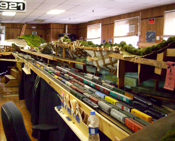
Of all the layouts, the HO scale layout is the largest and we have the most members. The layout takes up a 2700 square foot area and is designed as a walk-around type with two levels so the Engineers can follow their trains as they make their way along the route. The mainline track length is 4.91 scale miles long, or 297.98 actual feet. The distance of the Ohio River Subdivision run is 5.32 scale miles or 322.87 actual feet. The length of the C&O Portsmouth Subdivision is 1.86 scale miles or 112.88 actual feet long.
We have prototype operating sessions each month. (If you are an active Model Railroader and interested in attending one of our operating sessions, email operations@delmarvamodelrailroadclub.org or call 302-856-9250 for more information. You do not need to be a member of our club, although we would be delighted if you join.)
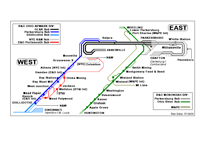
The track design of the layout loosely follows the Monongah division of the B&O Railroad as it was in the 1970’s. (See the map in the ‘Prototype Operations’ section for a routing of the track and the towns.) 70% of the Ohio River Subdivision is on the upper level. The staging yards at the East and West ends have two through tracks running through them so the layout can have multiple trains circling the layout during our open house days held during the Christmas Holiday Season each year.
This original and permanent club layout was not designed for operations, but instead as most layouts start out, was a Christmas tree loop or in this case 3 loops. The layout started as a double track “L” shaped loop with a single-track line making a loop somewhat in the middle. This was fine for open house displaying and for letting members just run their trains.
In the early 1990’s, a few members started thinking about trying to set up some type of prototypical operations on the existing layout where trains and cars would serve the existing industries. Walk around DC control and block control panels were added to the layout. Next, an operational scheme was devised and few sessions were tried with many problems found. The layout had many things that did not allow it to operate successfully, so operations stopped and reworking the problems started. The Railroad also needed a place to come from, and go to.
The place that seemed to fit what was there was Parkersburg, WV, right on the Ohio River along the WV & OH border. It appeared to have a PRR (Pennsylvania Railroad) junction across the river from Parkersburg. So after much discussion, it was chosen as a starting point. So the modeled yard would be Parkersburg and the junction on the layout would be Belpre. The existing main line was now the B&O main from Baltimore to St. Louis and PRR was given joint trackage rights into Parkersburg.
Also in 1997, plans where started for expanding the original permanent layout. These plans for expansion were a direct result of finding a “location” that the layout would represent. The modules were relocated in another area to make room for the new expansion, and to see what kind of room was available for it. As far as prototype operations were concerned, the layout, with the new expansion, would represent the B&O Railroad from Cincinnati OH to Grafton WV. An upper level was also planed, and this would be part of the Ohio River Subdivision from Hunting WV to Wheeling WV.
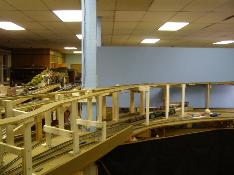
Construction was started on the new section in 2002. One mainline was completed and running for the December 2003 open house. In February of 2004, adding the second level was approved and the backdrop for the new section was started so it would support the upper level. Construction on the actual upper level started in February 2005.
In March of 2005, the West Junction track work was completed.
In 2008, 90% of all track work was completed plus some small amount of scenery in two locations was in work. Work continues on the large industrial areas and on the upper level representing the Ohio River Subdivision. Prototype operations are now being held once a month, and scenery work on the new section continues, as well as scenery re-work in the port area.
In early 2008, installation of DCC block detection and signals was started. Detection and signals were completed in the towns of Grosovneor, Athens, and Hamden in early 2009, and Belpre was selected next to be signaled and work started immediately after completing Hamden. To aid in operations and with the new signal system, a “tower” was built. This enabled the HO computer to be set up there with a magnetic dispatching board.
In 1984, when the club was first started, a small group of HO scale modelers started construction of a group of modules. These modules were portable and could be set up at different locations, and often were on display at various locations on DelMarVa. The HO modules in turn attracted more members to the club and HO scale modeling.
In 1985, after the club found a permanent home, a committee was appointed to design a large HO-Scale layout, and construction was started. Although it had very little scenery, in December of 1985, we had our first open house. The layout at that time was an L-shape with 2 proposed additions which was to make it E-shaped. However, it was decided that no additional areas will be started until scenery has been competed on the existing portions. Different modelers were assigned, or chose, different towns and sections of the layout to complete. As a result, some spectacular scenery has been constructed on the layout.
There was a fiddle yard area on the back of one leg of the “L”, so to make the loop point to point, the “fiddle” yard was cut in half and the loop opened up, at least on paper. With this done, there were now two staging yards, one at each end of the layout. So now there was a place to go to and come from.
In 1997, a digital control system was installed. This allowed more trains to be run on the same sections of track at the same time, which added to the operations that were being set up.
As part of operations, the layout needed a “place” to represent. But where was this place? There were some design elements already in place that had to be lived with, a small port with a yard, a yard with a wye that had a double track main on two of the legs and a single track main on the other leg. Other design elements included a junction of two double track mains (one of the double track mains goes to the new addition which at this time was not yet built), a small quarry line with a small town and yard also a busy port with a yard.
Operations on the Delmarva Model Railroad Club HO Layout
By Bill Deeter
The original club layout was not designed for operations but instead as most layouts start out, a Christmas tree loop or in this case 3 loops. The layout started as a double track “L” shaped loop with a single-track line making a loop somewhat in the middle. When I joined the club in the early 1990’s there were a few people (mostly Carl Wieland) interested in trying to make the layout usable for operations. Looking back I do not think that we would have the great operations base layout we have today without Carl. Carl lead the way to walk around DC control and adding block control panels to the layout. An operational scheme was devised and few sessions were tried with many problems found.
The layout had many things that did not allow it to operate successfully so operations stopped and reworking the problems started. On top of the mechanical problems the layout lacked a location and an identity if you will. Because of it being a club layout it had a generic everything. The layout had a eastern mountainous flavor set in the steam diesel transition with a double track loop with an unsceniced fiddle yard area on the back of one leg of the “L”. So to make the loop point to point the “fiddle” yard was cut in half and the loop opened up at least on paper. With this done we now have two staging yards one at each end of the layout. So now we had a place to go to and come from. But where was this place? There were some design elements already in place that had to be lived with, a small port with a yard, a yard with a wye that had a double track main on two of the legs and a single track main on the other leg.
Other design elements include a junction of two double track mains (one of the double track mains goes to the new addition which at this was not yet built), a small quarry line with a small town and yard also a busy port with a yard. Then there was the multiple favorite railroads of the members. Thankfully these were primarily northeastern roads, PRR (Pennsylvania Railroad) & PC (Penn Central), NYC (New York Central), B&O(Baltimore & Ohio) and C&O (Chesapeake & Ohio) to name just a few. We considered starting a freelanced layout but nobody really wanted to paint there loco’s in some custom scheme.
So the search for a prototype locale began. A copy of Kalmbach Publishing’s “1948 Handy Railroad Atlas of the United States” was used to look for something that at least resembled the design elements of the existing layout. The place that seamed to fit what was there was Parkersburg, WV right on the Ohio River along the WV & OH border.
It appeared to have a PRR (Pennsylvania Railroad) junction across the river from Parkersburg. So after much discussion it was chosen as a starting point. So the modeled yard would be Parkersburg and the junction on the layout would be Belpre. The existing main line was now the B&O main from Baltimore to St. Louis and PRR was given joint trackage rights into Parkersburg. As with most model railroads some modeler’s licenses had to be used. The chosen area is not all that popular among modelers and rail fans so not much info was readily available. Normally this would be a bad thing but since the layout was well established we could convert it to the B&O main and not many rivet counters will know anything about the real area. The visible yard on the layout was turned into Parkersburg, WV with east staging being Clarksville and the west staging being B&O in Cincinnati, OH & PRR in Zansville, OH. A fictitious branch line was created for the single track out of Parkersburg to the port.
As mechanical work continued the operations planning also continued. Waybills were created for industries on the layout and off line. The four-sided waybills were created with Sheneware’s Waybill program and printed on blank business cards. A database of rolling stock using Excel was created and a word template was used to create the car cards for each train car. Train numbers and a schedule were created and when enough repairs had been done operations started again. In those days five people at an ops session was a great turn out. Click this link to view and download a file on how to read the Waybills as used by the DelMarVa Model Railroad Club.
Even though the layout has a decent main line track length it did not give the feel of operating a major railroad main line. It was now time to work on the plans for the layout addition. Different track plans were drawn and more research was being done on the area. A form 6 was obtained as well as B&O Freight Schedule and Classification Book and a couple of Employee Time Tables.
The modeled portion of the layout became the Parkersburg Subdivision of the B&O Railroad’s Ohio-Newark Division. This could not have worked out better if it was really planned this way. What we now have is the entire Parkersburg Subdivision modeled on the layout. We have a run from Division point yard to division point yard on the layout. The division point run is between Parkersburg WV and Chillicothe, OH. There is also a short section of the OL&K sub of the Ohio-Newark Division running from Parkersburg through Belpre to Zanesville (staging) This section also has joint trackage rights with the PRR into Parkersburg. Modeler license was used for the joint trackage rights but it was not that far of a stretch as part of this line does have joint trackage rights.
We have a short distance of the Monongah Division‘s Parkersburg Sub modeled on the layout. This is the area of double track main east of Parkersburg WV to Grafton WV (staging). The Ohio River Sub from Wheeling to Huntington WV is also modeled on the layout.
The port has become the Lower Yard of Parkersburg on the Ohio River Sub of the Monongah Division running through the High Yard of Parkersburg following the existing branch onto the second level of the new section of the layout to Hunting WV (staging). The Ohio River Sub runs the entire length of the new layout on the second level.
As part of our operations, we are in the process of developing a Timetable that parallels the real ones. Click this link to download the Timetable in PDF format.
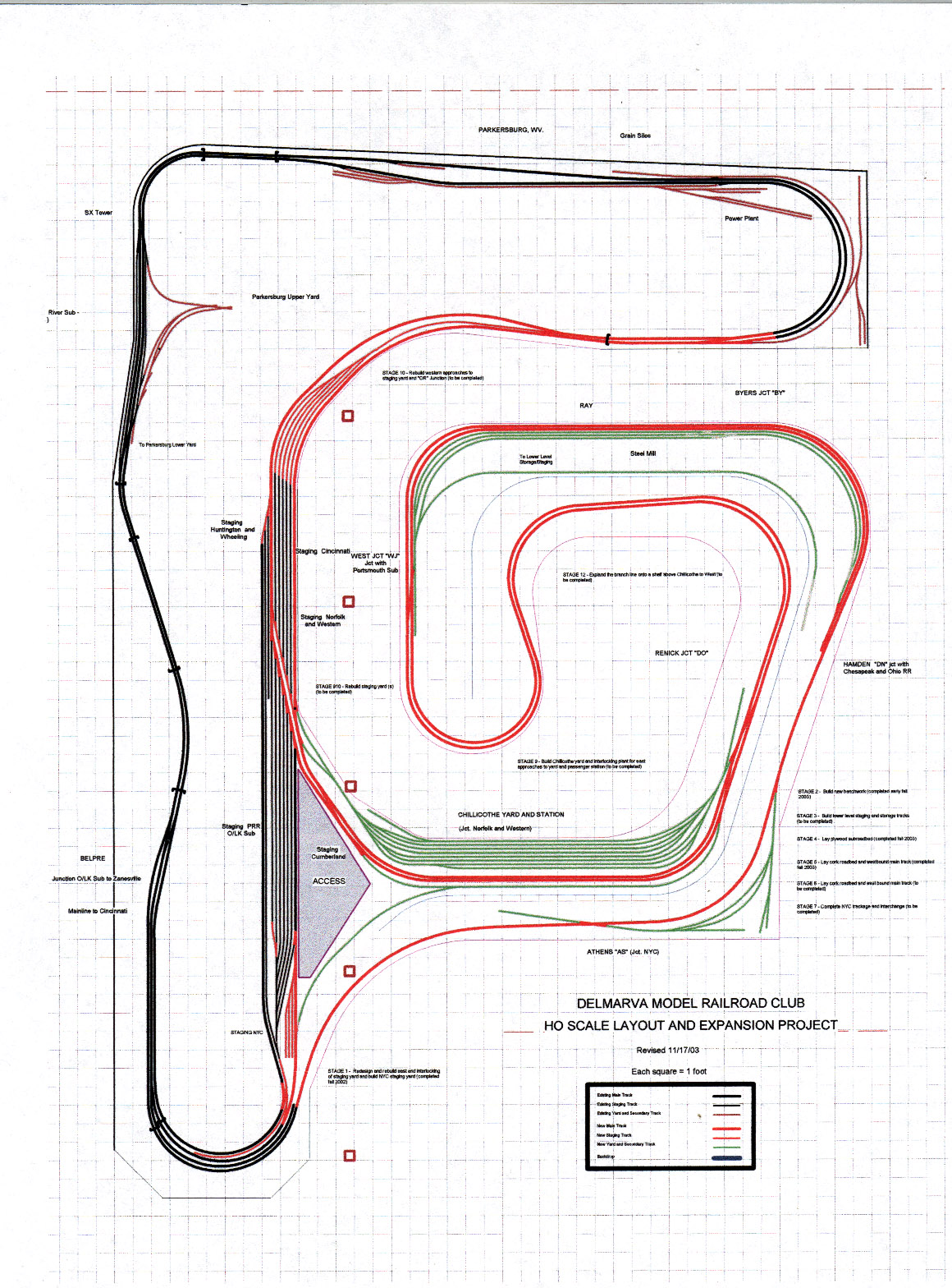
The diagram above is the current track plan of the layout. Not all industry tracks are shown, but all of the mainline is. Also, the main yard track plan at Parkersburg is not shown. This was the main drawing that the expansion was built to.
Train control on our layout is by Digital Command Control (DCC). This allows individual control of trains, independently on the same section of track. Think of this system as a set of transmitters and receivers. The transmitter being the hand held throttle that controls one locomotive, and the receiver being in the locomotive. Each receiver is known as a decoder and has it’s own unique address. The throttle can select one or more locomotives to control by “dialing up” or selecting the address of the locomotive decoder. To make things simple, the decoder address is usually the same as the locomotive number that is displayed on the locomotive. DCC allows control of our model trains just like the real trains run. That means that you can have train wrecks just like real trains can. So the engineers have to watch the tracks ahead, just like real engineers do.
Our DCC system is made by Digitrax. As such, there are numerous accessories that can be added to the system so that it can be expanded as large as needed, almost without any limits. Some of the accessories include Power Boosters to increase the current needed to run many locomotives, turnout controllers, signal decoders, block detectors, and more.
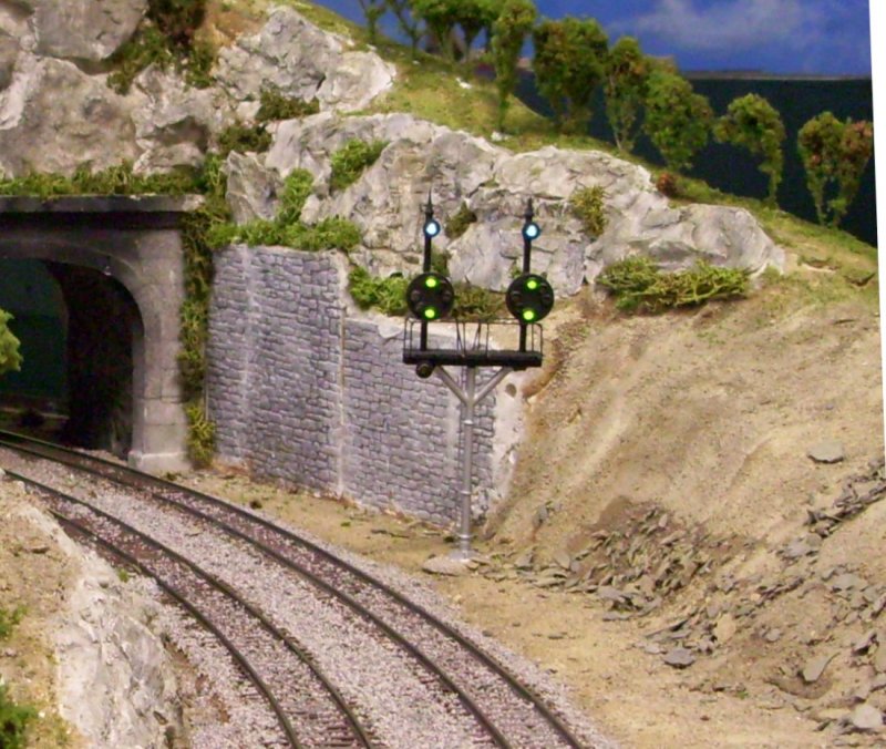
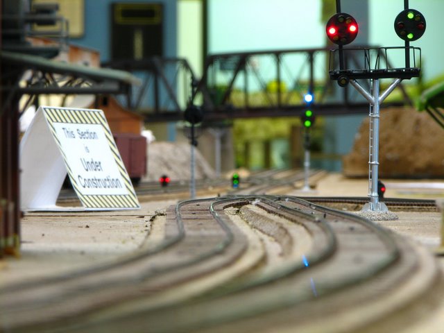
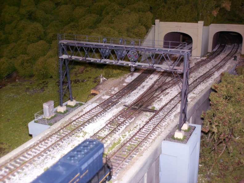
As part of it’s operations, as well as scenery, the club is planning, and adding, block detection, signaling, and a CTC display. Since our Model Railroad is modeling a portion of the B&O Railroad, the signals used will be B&O CPL (Color Position Light) signals. These are unique in their design.
Just what the heck are CPL signals anyway?
Essentially, CPL’s are COLOR POSITION LIGHT signals. That is, the information is conveyed to the engineer in three ways. One is by the COLOR of the lights. Green, Yellow, Red, or White. The second way is by the POSITION of the lights. Vertical (|) for proceed, Angled down right to left (/) for Approach, Horizontally (-)for Stop, and Angled down left to right (\) for Restricted. The third way is by LIGHT. One of the things that may be helpful to know at this point is, that before the B&O installed it’s CPL signals, they used Semaphore signals. A Vertical board was proceed, Angled for approach, and Horizontal for stop. So the designation of LIGHT was most likely to differentiate the new signals from the older semaphores. Also, the B&O uses “Marker Lights” in addition to the main signal head, and may have had something to do with the LIGHT designation in the CPL name. These “Markers” also convey information to the engineer. In most cases, this information is “speed”. In it‘s simplest form, they modify the “normal” speeds of the track the train is about to run on, once past or near the signal. The meaning of the B&O signal aspects and markers, as we will use them on our layout, will be slightly different than in the real world. If we were to implement our signals as the real B&O has, it would take an actual “rule book in hand” to figure them out, and that would not be fun. So we are going to simplify their meanings for our use on the HO layout.
What is being planned?
In the first step of the process, we have to have a plan for what signals we need and where they will be located. This is being done at this time for the whole layout, even though we are starting at the Athens – Hamden area. The layout is being divided into major areas that are logical to existing towns and major switching locations. At present, the areas are as follows: Renick Junction, West Junction, Athens, Hamden, Belpre, Parkersburg, Pensboro, and the Portsmouth Sub. The size of these areas is dependent on the capability of the circuit boards that have been chosen.
What is involved in the system?
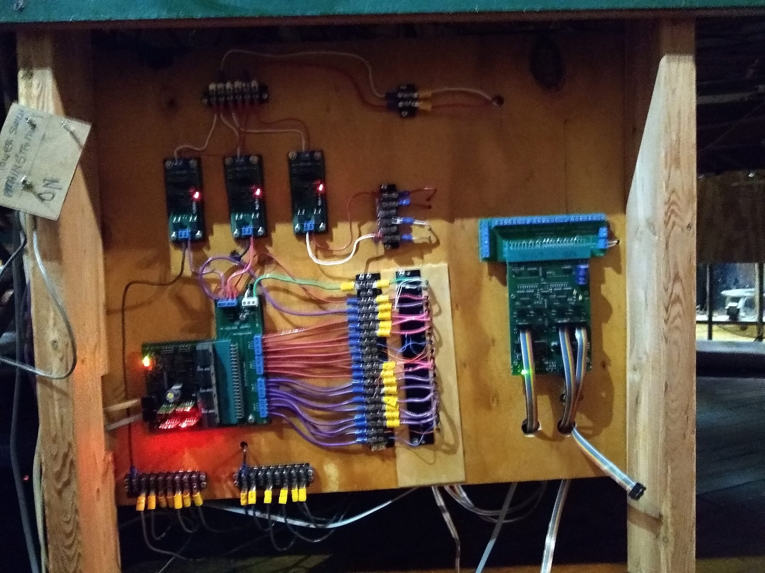
Of course we have to have the signals, and a means of operating or controlling them. The signals are being scratch built using brass tubing and other commercial parts and castings. LED’s are being used for the “bulbs”. The SE8C signal board by Digitrax has been selected to handle lighting and operating the signals. One SE8C board can operate up to 32, three aspect signal heads. (A three aspect head is one that shows Green, Yellow, and Red indications and can be in any physical configuration.) This does not include the “markers”. The markers will be set up as a second signal head where green will light the top marker, yellow will light the lower marker, and red will turn the markers off.
We also need a means of detecting where the trains are at, so the tracks on the layout must be divided up into Blocks and connected to another board that tells us what tracks are occupied with a train. For this “block detection” we have chosen to use the BDL168 detector board, also by Digitrax. This board is capable of detecting up to 16 blocks.
How they will be operated?
The signals will be operated by a computer through a program that is tied into the Digitrax LocoNet. At the present time we are using JMRI’s Panel Pro program. The program will be able to “read” which tracks are occupied and then tell the SE8C signal board what signals to set with what aspects.
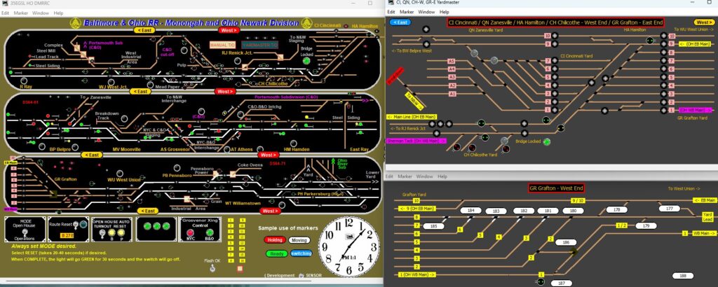
Here is a 2026 view of the three JMRI panels in use. These panels control the turnouts and show train occupancy status. The left one is the mainline dispatch panel. The two panels on the right are primarily used in tablets. The top one is for the Cincinnati staging yard. The bottom one is for the Grafton staging yard.
We are also planning to be able to control most mainline turnouts with the same computer program. These same turnouts will also be able to be controlled from a “local” control panel in the area that the turnouts are in. Thus the computer is not taking individual control away from operators and engineers. But by having computer control over some turnouts, it will provide the Dispatcher with the ability to route trains around other trains that may be switching or are slower. So you as an engineer of a mainline train, will be able to watch the signals and be automatically routed through an area that may be congested rather than having to call the Dispatcher. We have preliminary selected a board for turnout control which is the DS64, also by Digitrax. Turnout machines now in use would not normally have to be changed out. Only the control wiring would have to be changed.
Once each area is completed, an engineer will be able to run their train similar to the way it is done on the real railroads. That is by following the “Rule Book” and watching the Signals. Now this doesn’t mean that we are going to implement a “Rule Book” with a strict set of rules and associated tests for engineers and train crews just so you can run a train around the layout. However, the main things that any engineer should know are: What the speed limits are in each district he runs in; and What the signal aspects and indications mean. As the speed of a scale model train is subjective, no one is going to be at each location telling you that you are going too fast or too slow down. That would be no fun at all, and Model Railroading is supposed to be fun, and we want to keep it that way too.
What you can expect to see?
So the first thing that you will notice when running in a completed and signaled area is that when you pass a green signal, it will change to red, indicating that the block you just entered is now occupied with your train. When you leave that block, the signal will either turn back to green, or turn to yellow. So now you will be able to tell if there is a train in front of you, and if the signal is red, you should stop for it and not go past it. When it turns yellow or green, you may proceed according to the aspect given by the signal.
Also, once the mainline is completely signaled, all of the trains may be able to be run by the computer and not run into each other. They will automatically slow and stop for yellow and red signals, and then go again when the signal turns green. This will allow us, as club members, to be able to watch the trains run and spend time talking to our visitors at open houses.