|
|
HO |
|
We meet every Wednesday Night at 7:30 pm for Work and Fun at 103 State Street, Delmar,DE.
Come and join us. The Entrance is through the Red Door next to the Alley and then Up Stairs.
|
Control and Electronics
Train control on our layout is by Digital Command Control (DCC). This allows individual control of trains, independently on the same section of track. Think of this system as a set of transmitters and receivers. The transmitter being the hand held throttle that controls one locomotive, and the receiver being in the locomotive. Each receiver is known as a decoder and has it's own unique address. The throttle can select one or more locomotives to control by "dialing up" or selecting the address of the locomotive decoder. To make things simple, the decoder address is usually the same as the locomotive number that is displayed on the locomotive. DCC allows control of our model trains just like the real trains run. That means that you can have train wrecks just like real trains can. So the engineers have to watch the tracks ahead, just like real engineers do. Our DCC system is made by Digitrax. As such, there are numerous accessories that can be added to the system so that it can be expanded as large as needed, almost without any limits. Some of the accessories include Power Boosters to increase the current needed to run many locomotives, turnout controllers, signal decoders, block detectors, and more.
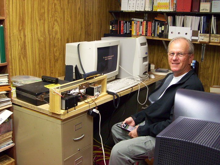
Member Steve working at the off-layout DCC programming track
As part of it’s
operations, as well as scenery, the club is planning, and adding, block
detection, signaling, and a CTC display. Since our Model Railroad
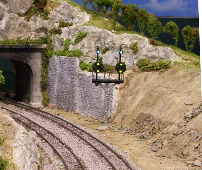
is modeling a portion of the B&O Railroad, the signals used will be
B&O CPL (Color Position Light) signals. These are unique in
their design.
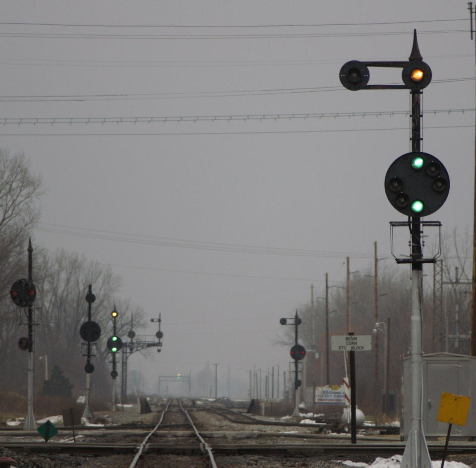
A series of B&O CPL signals protecting a crossing
Just what the heck are CPL signals anyway?
A “Full” CPL with all of the lights and markers possible
What is being planned
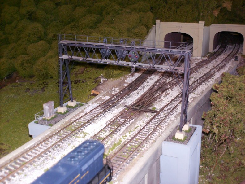
HO Scale B&O signal bridge at Belpre.
What is involved in the system
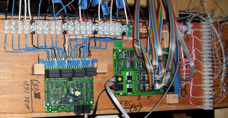
Of course we have to have the signals, and a means of operating or controlling them. The signals are being scratch built using brass tubing and other commercial parts and castings. LED’s are being used for the “bulbs”. The SE8C signal board by Digitrax has been selected to handle lighting and operating the signals. One SE8C board can operate up to 32, three aspect signal heads. (A three aspect head is one that shows Green, Yellow, and Red indications and can be in any physical configuration.) This does not include the “markers”. The markers will be set up as a second signal head where green will light the top marker, yellow will light the lower marker, and red will turn the markers off. We also need a means of detecting where the trains are at, so the tracks on the layout must be divided up into Blocks and connected to another board that tells us what tracks are occupied with a train. For this “block detection” we have chosen to use the BDL168 detector board, also by Digitrax. This board is capable of detecting up to 16 blocks.
BDL-168 Detection Board on Left and SE8C Signal decoder on the Right.
How they will be operated
The signals will be operated by a computer through a program that is tied into the Digitrax LocoNet. At the present time we are using JMRI’s Panel Pro program. The program will be able to “read” which tracks are occupied and then tell the SE8C signal board what signals to set with what aspects.
This
is a view of the Computer Display for the layout. Currently, only
the middle window is active with block detection, signals, and turnout
activity. The white lines represent the Mainline tracks.
The tan lines represent all other tracks. The main signal
aspects are indicated by the larger circle of the signal, while the
marker light aspect is indicated by the smaller circle under the larger
circle. Not all CPL signals allow control of the markers, thus no
markers are shown on some signals. The three other types of
signals shown are the Dwarf Signal, the C&O type signals, and the
NYC type signals.
We are also planning to be able to control most mainline turnouts with the same computer program. These same turnouts will also be able to be controlled from a “local” control panel in the area that the turnouts are in. Thus the computer is not taking individual control away from operators and engineers. But by having computer control over some turnouts, it will provide the Dispatcher with the ability to route trains around other trains that may be switching or are slower. So you as an engineer of a mainline train, will be able to watch the signals and be automatically routed through an area that may be congested rather than having to call the Dispatcher. We have preliminary selected a board for turnout control which is the DS64, also by Digitrax. Turnout machines now in use would not normally have to be changed out. Only the control wiring would have to be changed. Once each area is completed, an engineer will be able to run their train similar to the way it is done on the real railroads. That is by following the “Rule Book” and watching the Signals. Now this doesn’t mean that we are going to implement a “Rule Book” with a strict set of rules and associated tests for engineers and train crews just so you can run a train around the layout. However, the main things that any engineer should know are: What the speed limits are in each district he runs in; and What the signal aspects and indications mean. As the speed of a scale model train is subjective, no one is going to be at each location telling you that you are going too fast or too slow down. That would be no fun at all, and Model Railroading is supposed to be fun, and we want to keep it that way too.
What you can expect to see
So the first thing that you will notice when running in a completed and signaled area is that when you pass a green signal, it will change to red, indicating that the block you just entered is now occupied with your train. When you leave that block, the signal will either turn back to green, or turn to yellow. So now you will be able to tell if there is a train in front of you, and if the signal is red, you should stop for it and not go past it. When it turns yellow or green, you may proceed according to the aspect given by the signal. Also, once the mainline is completely signaled, all of the trains may be able to be run by the computer and not run into each other. They will automatically slow and stop for yellow and red signals, and then go again when the signal turns green. This will allow us, as club members, to be able to watch the trains run and spend time talking to our visitors at open houses.
HO Scale CPL's on a "Wye" pole.
|