Signals For Your Model Railroad - Getting Started
By Elmer McKayThere are different degrees of signal system complexity for model railroads. The simplest being a signal that changes colors when a turnout is thrown. The more complicated are the ones that need a computer to tie together block occupancy and turnout direction. And there are signal systems that fall in between. The systems that utilize a computer are the most realistic, and the most expensive. If you want to add a signal system controlled by a computer, your DCC system should be capable of connecting to the computer also. Some beginner or entry level DCC systems can not be connected to a computer, but most of the advanced systems can be. Be sure to check your system before purchasing parts that you may not be able to use.
Another consideration of the type of signal system to choose is your ability to understand electronics and wiring. If you have a problem setting the clock on a VCR or DVD player, or if you still do not understand your own DCC system, stay with the simplest type of signal system, one that does not require a computer.
Type of Signals to Use
If you don't know anything about railroad signals and how they are used, you need to do some research to find out. Railroad signals are not traffic lights. They came before traffic lights, and the green, yellow, and red aspects (signal colors) mean different things. Some signal masts have two signal heads mounted on them. These usually indicate a diverging route of the track at a turnout. Signaling can be a hobby within a hobby, and to do it right takes research. The Internet is a valuable resource and you should take full advantage of it. Different railroads use different types of signals, so if you are modeling a particular prototype, you need to know what type of signals they are using. If your model railroad is freelance, like mine is, you need to decide what type of signals you want to use, then find a railroad that uses or used that type and research them and how the signals operated.
The following links will get your research started:
http://www.railroadsignals.us/
http://www.lundsten.dk/us_signaling/
Signal Plan
The first thing that you need to do when wanting to set up signals for your layout is have some kind of "Signal Plan" for your model railroad. You must decide what you actually want to do. As an example, on mine, I have the railroad divided into blocks. These blocks are detected blocks so when a train is in them, a signal is sent to a computer program. (Block detection can be simplified by saying it is train detection.) Also, when a turnout is thrown or changes position, a signal is also sent to the computer program. Then I have signal boards that connect to my signals and will make the colors of the signals change as these different things happen. The signals are wired to the signal boards and are controlled by the computer program.
The first step in making a signal plan is to draw a track plan of your model railroad, then decide where you want to put your signals (as determined by a real railroad). Next, decide what is going to make the signals change. Either when a train is in a block, in an OS section (A block made up of turnouts, referred to as "On Switch" sections.), or when a turnout changes; or all of them together. Once you do that, you will have a better idea of how many signals you will need, how many sensors or controls will be needed for turnout positions, and how many blocks will be needed to detect your trains.
As to how long a block should be, it is up to the person building the layout and how much track they have on the mainline. The length of the trains that you run can usually help determine the length of the blocks. One desire is to be able to fit a complete train in a passing siding. Another is that the mainline can be divided up into a number of separate blocks if there is enough distance from one passing siding to the next. Some people make the length of their blocks one train length long, and some make them two train lengths long, and some make them shorter or longer. I run short trains on my layout, 6 to 8 cars with one locomotive and a caboose. My mainline blocks are at least one train length long, and usually not longer than two train lengths.
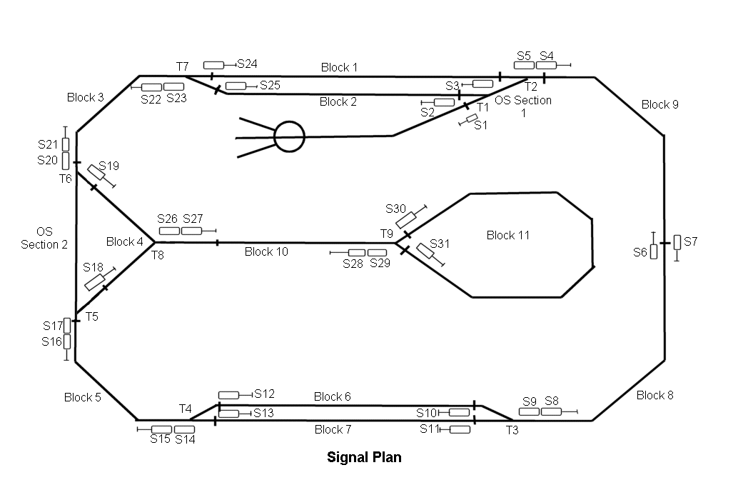
At this time it may be a good idea to decide if you are going to go "whole hog" or do something simpler with your signal system. An example of a signal plan is shown below. It shows where the rails are gaped, the blocks and their ID numbers, the turnouts and their ID numbers, and the signals with their ID numbers. When developing the plan, place the signals first according to the signal practices of the railroad you are modeling. Then you can indicate the gaps that are required to make it work. The logic that makes it all work is associated with the computer program that you choose.
 |
Block Detection
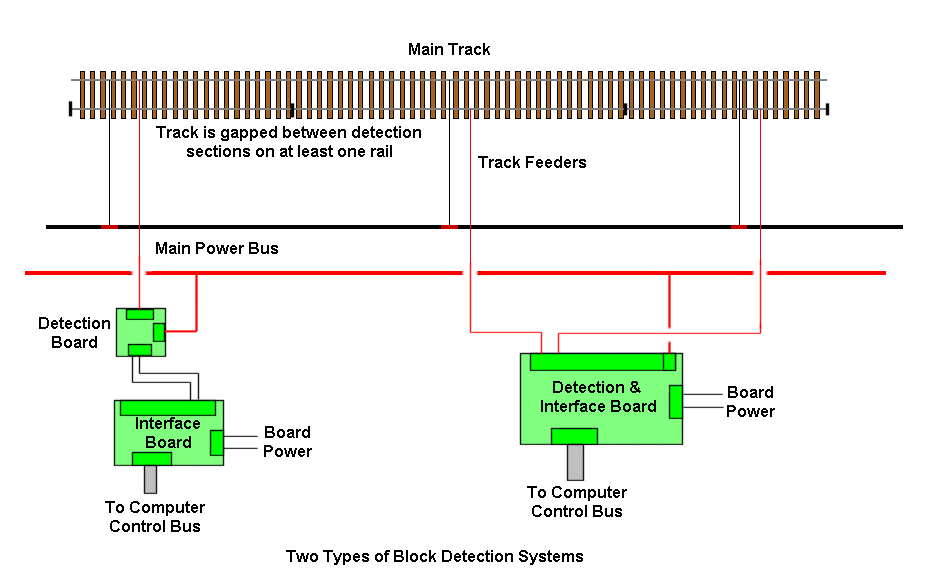
A system for detecting when a train is in a block or on a certain section of track is necessary. For current type detection, the track must be gaped on one or more rails, according to what the block detector manufacturer advises for their system. There is also block detection that uses photo-cells or IR type devices. There are different types to choose from and each manufacturer has their own version and style, so some research is in order to see which one will work with the DCC system that you have.
 |
Turnout Position Detection
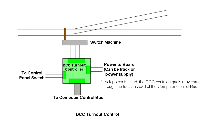
You should know what position your turnouts are in also, because this affects the signal aspect or color. This can be done by wiring the auxiliary switches on a turnout machine to an input of some type, or some systems will use the same computer signal that is sent to the DCC turnout controller when throwing a turnout.
 |
Signal Board
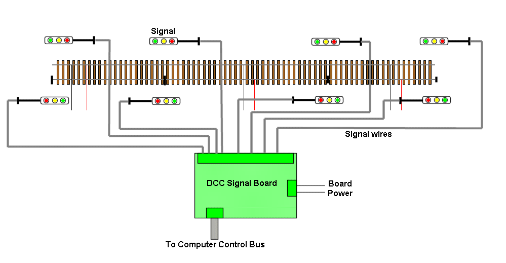
The signal board takes the computer signal and makes the signals display the aspects or colors that the program says they should be. Signal wiring can be intense. Some systems are modularized to make the wiring easier.
 |
Computer Program
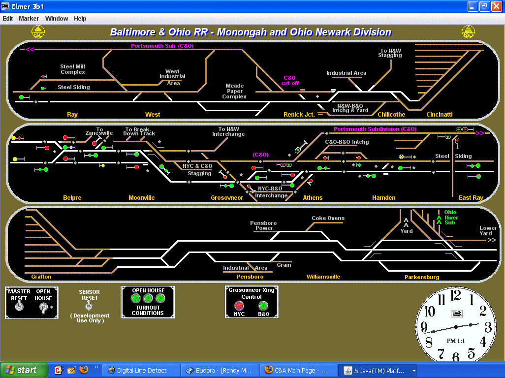
The computer program controls the system. It looks at the blocks, if occupied or not; looks at the position of the turnouts; and looks at any other sensor indications that are being sent to the computer. The Logic in the program takes all of these inputs, tests them with the program logic, and then sends the appropriate commands to the signal board to light the signals with their proper aspects or colors. The computer panel shown below was designed using JMRI Panel Pro. JMRI also provides the logic for everything to work. When turnouts are thrown, blocks occupied by a train, and the signals change, the display icons change to reflect these events. This panel is currently being built and modified as more block detection and signals are added to the railroad. The center window is the most complete.
 |
Equipment Types
There are different manufacturers that make boards for block detection, turnout control, and signal display. You will have to choose which ones that you want to use. Here are some web sites out of many available.
http://www.wiringfordcc.com/signaling.htm
http://www.logicrailtech.com/index.htm
http://www.circuitron.com/index.htm
http://home.cogeco.ca/~rpaisley4/CircuitIndex.html#index
http://www.cti-electronics.com/
http://www.rr-cirkits.com/
http://www.digitrax.com/menu_detectionsignaling.php
As far as the equipment is concerned, both the signals and the electronic boards make it all happen. Once you pick a company for your parts, you should stay with that company if possible. It will make things easier as you build your signal system.
You will also need to select a computer program to run your signal system. That means that you will need a computer. As far as programs go, there are several to choose from, including JMRI Panel Pro which is free.
http://jmri.sourceforge.net/
http://www.freiwald.com/
The System I use
I have decided to use Digitrax products for my signal system. My railroad is 24 foot by 9 foot and my signal plan called for 32 blocks, 28 to 32 sensed turnouts, and 43 signals, 12 of which have two signal heads for a total of 55 signal heads. Thus I have decided to use 2 Digitrax BDL-168's, for a total of 32 detected blocks; one DS64 for 4 turnouts - 2 of which are crossovers that control two turnouts each; and 3 Digitrax SE8C's, for 24 more turnout controls, 24 sensors (not all being used), and 96 signal heads (not all being used). (If you want to know more about these Digitrax boards, you can download all of their instructions from the Digitrax web site.) The Digitrax SE8C is a multiple use board. One SE8C will control 32 signal heads (different than 32 signals), 8 Tortoise switch machines, and has 8 inputs for additional sensors. -OR- The SE8C can be used to control semaphore type signals that use Tortoise switch machines to make the signal blades move. There are other manufacturers that make and sell block detection boards, turnout decoders, and signal decoder boards for DCC. The choice is yours, so again, do your research.
To use the Digitrax boards,I had to set up a stand-alone LocoNet. The following link shows how I did it. Note that if you want to do the same thing, you should have some understanding of wiring and be able to read and interpet instructions. This is not like building a plastic kit where you can just look at the parts and figure it out.
LocoNet for non-Digitrax Layouts.
So as you can see by this time, adding working signals to a model railroad is not cheap, and it is not simple either; but once built, installed, programmed and operating, they add some realism that would be hard to duplicate.