Servo Mounting and Link System
byElmer McKay
In the quest
for reliable and cheaper (inexpensive) turnout machines, a fairly new
company has come forth. Tam Valley. They are making several
products that enhance the world of electronics for model railroaders. One being several different types of controllers for allowing the use of inexpensive
model airplane servos as turnout machines. Since the Tortoise showed up on the market with their new type of control arm to the turnout, it seems
that everyone has lost sight of the old reliable turnout throw linkage that has been in use for decades prior to the introduction of the Tortoise.
Tam Valley in its effort to keep up with the times has designed a mounting system that mimics the tortoise linkage. This is all well and good, but in
my opinion, it is not the best linkage that could be used. The old linkage of a torsion wire in a tube is better. The following photos, drawings, and
descriptions of this link and servo mounting system are explained in detail.
Figure 1 above shows the parts of the linkage system. As
you can see, no large hole under the turnout throw bar is needed.
This linkage is
installed after the turnout is in place. Is there a disadvantage? There can be. With no hole in the layout under the throw bar, loose ballast can
accumulate there and possibly jam the throw bar. The key to preventing that is not to apply or glue your ballast in the area where the throw bar
is. Also, after the ballast glue has dried, vacuum up any loose ballast around the turnout.
a slight amount. This is about 1/8th of an inch. The distance labeled 'B' is the length of the servo arm used from the arms mounting screw to the last
hole in the arm. This distance is not critical, but should be as close as you can get it, and will have to be bent while working under the layout.
Distance 'C' is slightly shorter than length 'B', but can be the same length for ease of cutting.
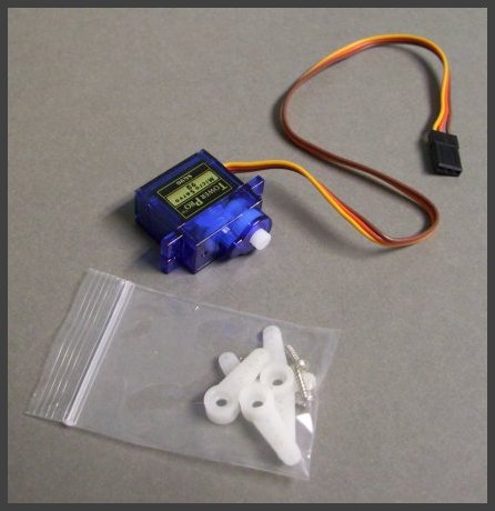
This is the servo and the parts that come with it. You can get them as cheap as $2.50 each.
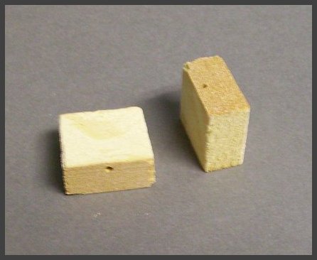
We will use two small wood blocks to mount it. Note that the blocks have pilot holes drilled for the mounting screws.
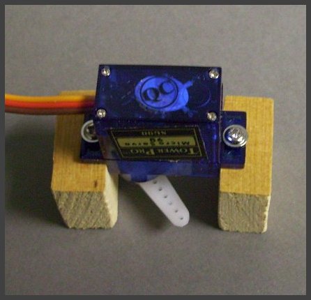
Mount the servo to the blocks, then put the control arm on and secure it with the screw provided.
This photo also shows the size of the wood blocks in relation to the servo. The height of the blocks is 3/4 inch.
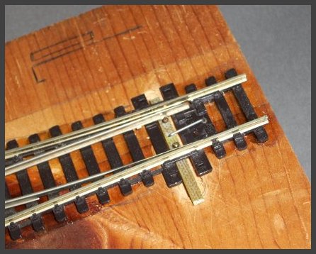
In this HO scale installation, we have drilled the hole for the tube through a plastic tie.
Insert the tube, glue it in place (we used super glue) and cut off the excess under the layout.
Bend the wire in a square U shape. The short bend goes in a hole in the throw bar, the long bend goes in the tube.
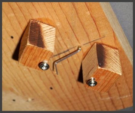
This is under the layout. With someone holding the wire down at the throw bar on the top of the layout, bend the wire
90 degrees right at the tube. This bend will now keep the wire from moving up and down, and will maintain the short
bend on top in the throw bar. Now make the second bend. These bends are done without the servo being mounted yet,
so the wood blocks seen in this photo would not be there yet.
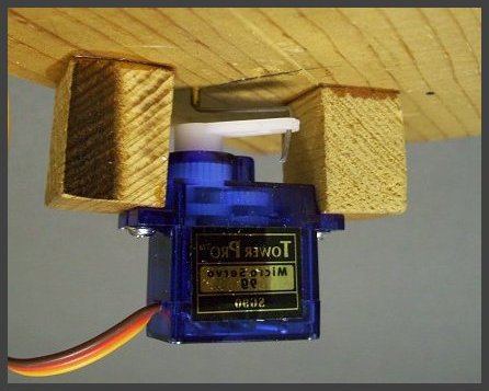
To mount the servo assembly, fit it in place first to make sure everything is OK. Then apply medium super glue
to the top of the wood blocks, re-fit the servo assembly in place, and hold until the glue cures. This usually takes
about 30 seconds. You can also spritz it with CA kicker for a faster glue cure time. If you ever have to remove the servo
for any reason, just undo the two servo mounting screws and it will come right out.