Elmer McKay
Electrical Remote Control for our turnouts is nice, but sometimes we want something simpler. When serious Model Railroading was starting just after WWII, an automobile choke cable was used as a simple mechanical means to control turnouts. This was even before the days of twin coil switch machines. These devices are still applicable today, although they have a new form. Today you can buy nylon tubing in different sizes so you can make your own, or simply buy Gold-N-Rod cables as used in model Radio Control Airplane controls. http://www.sullivanproducts.com/GoldnRodMainFrame.htm The information on this page will describe how you can make a simple manual control device for your turnouts on model railroad.
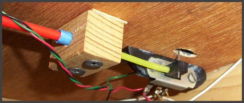
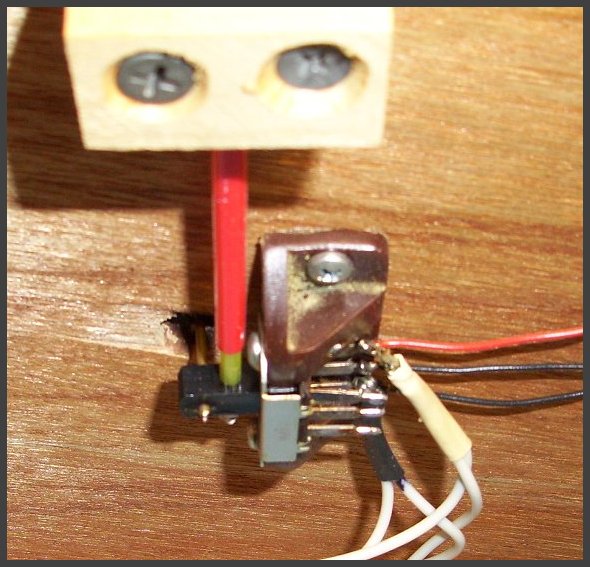
The main part of the device is a standard size slide switch. The slide switch moves back and forth. If it is attached to the bottom of your layout under a turnout throw bar, a stiff wire could be inserted into the handle and move the throw bar of the turnout. The following photos show how this can be done.
As you can see,
if you push or pull the rod (yellow) the slide switch will move back
and forth, the wire up to the throw bar will also move back and forth.
Since the slide switch is an electrical switch, it can also be
used for
hooking up some type of indicators such as LED's.
The outside rod is red, the inside rod is yellow. The wood block holds the outside rod in place. The switch handle is clearance drilled for a 2-56 screw, which is then inserted through the switch handle and screwed into the yellow rod.
The slide switch is held in place by a cast resin block. It can also be held in place by gluing the switch directly to the bottom of the layout, or by cutting some angle aluminum and making a holder from it.
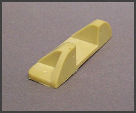
The cast resin Switch Holder.
Because I used quite a few of these manual turnout devices, I made a master of the switch holder and cast them myself.
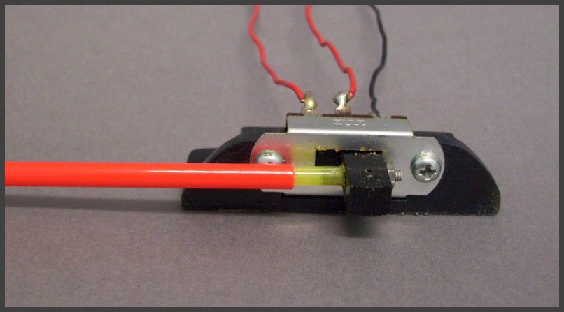
The parts before mounting to the layout. Note the small hole in the top of the handle. This is for the wire, usually piano wire because it is very stiff.
Note that in this photo, a brass tube is also in the switch handle. This increases the stiffness of the wire if needed.

The outside rod is red, the inside rod is yellow. The wood block holds the outside rod in place. The switch handle is clearance drilled for a 2-56 screw, which is then inserted through the switch handle and screwed into the yellow rod.
The slide switch is held in place by a cast resin block. It can also be held in place by gluing the switch directly to the bottom of the layout, or by cutting some angle aluminum and making a holder from it.
The cast resin Switch Holder.
Because I used quite a few of these manual turnout devices, I made a master of the switch holder and cast them myself.
The parts before mounting to the layout. Note the small hole in the top of the handle. This is for the wire, usually piano wire because it is very stiff.
Note that in this photo, a brass tube is also in the switch handle. This increases the stiffness of the wire if needed.